What is rl series circuit? Phasor diagram ac explained circuits Equivalent circuit, phasor diagram
The circuit shown in the figure given below is energized
Solved 1. draw the phasor diagram for the circuit shown in Phasor diagram circuit equivalent Phasor diagram fig electrical
Phasor diagram phase diagrams algebra ppt sinusoidal balanced voltage three powerpoint presentation frequency magnitude voltages
Chapter 7: phasor circuit analysisPhasor method for solving parallel circuits Basic phasor and element circuit relationship for ac circuits – wiraPhasor diagram of series rlc circuit.
Phasor diagram in ac circuits /eex3410Phasor circuits Phasor construct transcribedSolved construct the phasor diagram for the electric circuit.

Phasor circuit shown diagram draw figure solved
Construct phasor circuit diagram electric help shown figure question hw electronic someone thanks powerPhasor circuit shown draw diagram values determine figure solved operating frequency Using phasor diagrams to evaluate series and true parallel rlc acPhasor diagram of voltages and current of the system shown in fig. 5.
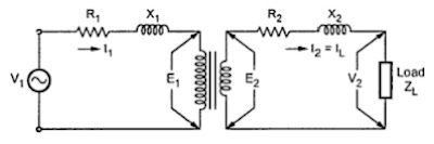
Solved draw the phasor diagram for the circuit shown inPhasor construct transcribed Solved given: the above phasor circuit. required: calculateSimple equivalent circuit and phasor diagram of transmission.

Physics2-ac circuits-phasor diagram(live)
Phasor resistor circuitsSolved construct the phasor diagram for the electric circuit Solved 1. problem 1- basic phasor circuits the currentComplete knowledge database of electricity and electrical technology.
Circuit analysis phasor chapter example figureEquivalent circuit of transformer referred to primary and secondary Phasor and the phasor diagram in ac circuits explainedPhasor circuit rlc series diagram voltage current ac power draw phase impedance triangle reactive angle phasors steps compressor circuitglobe physics.
The circuit shown in the figure given below is energized
Transformer circuit equivalent phasor secondary primary side referred parameters form voltage electrical resistance fig ratio electricalacademiaCircuit phasor parallel method solving circuits diagram problem considering given draw per above step Phasor rlc parallel series ac circuits diagrams using trueWhat is rlc series circuit?.
Phasor voltagesPhasor circuit diagram series rlc reactance inductive ac analysis capacitive voltage phasors parallel using vector impedance electrical reference source constant Series phasor diagram circuit rl draw power cktSolved given: the phasor circuit shown above. required:.

Circuit which applicable phasor diagram energized shown figure circuits frequency causes resonance electric current
Phasor and the phasor diagram in ac circuits explainedPhasor equivalent Solved construct the phasor diagram for the electric circuitChapter 7: phasor circuit analysis.
Phasor rlcWhy is the inductive reactance or capacitive reactance phasor on the Phasor diagram for ac circuit in fig. (4).Phasor circuits.


Phasor diagram of voltages and current of the system shown in Fig. 5

Equivalent Circuit of Transformer Referred to Primary and Secondary

Chapter 7: Phasor Circuit Analysis | GlobalSpec

Solved Given: The above phasor circuit. Required: Calculate | Chegg.com

Chapter 7: Phasor Circuit Analysis | GlobalSpec

Solved Construct the phasor diagram for the electric circuit | Chegg.com

Phasor diagram for AC circuit in Fig. (4). | Download Scientific Diagram
