Full-wave bridge rectifier Simple bridge rectifier circuit Full wave bridge rectifier
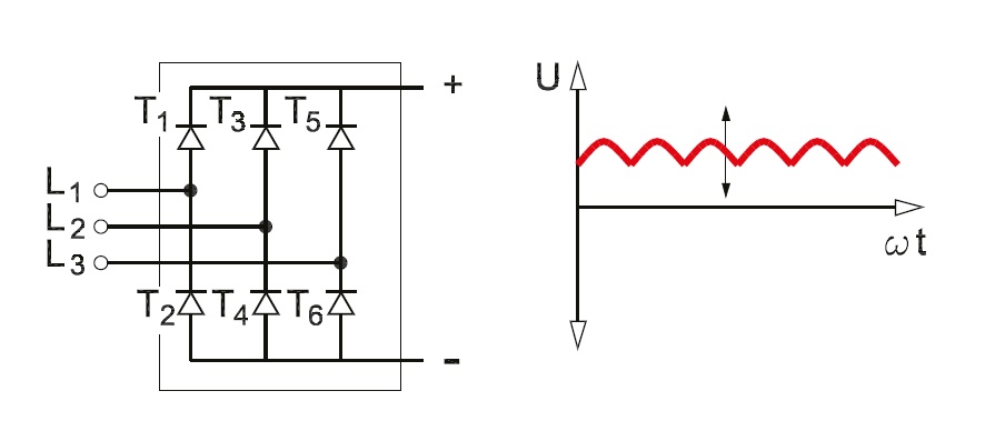
Three Phase Full Wave Rectifier Working, Diagram and output waveform
Circuit analysis Full wave bridge rectifier operation What should i consider when choosing the right diode…
Rectifier tapped circuitstoday waveform diode multisim operation voltage repix
Draw a circuit diagram of a full wave rectifier. e toppr.comRectifier wave bridge circuit diagram peak voltage diode disadvantages advantages Full wave bridge rectifier – circuit diagram and working principleGeneral circuit diagram of the bridge rectifier (a) full wave bridge.
Rectifier circuit diagram wave output waveform inputPhase control wave dc rectifiers power ac explained minutes Rectifier input explain waveforms diodes topprFull wave bridge rectifier.

Rectifier circuit diagram
Full wave bridge rectifier – circuit diagram and working principleRectifier circuit wave Rectifier principle understanding simplify lookedFull wave rectifier circuit diagram in multisim.
Phase control rectifiers explained in 2 minutesRectifier bridge wave Rectifier diode rectifiers circuitsRectifier principle.

Three phase full wave rectifier working, diagram and output waveform
Rectifier wave bridge circuit diodes operation negative forward becomes its figure below biasedRectifier phase controlled wave waveform output rectifiers Rectifier wave bridge operation half animation input working cycle current positive forward during gif diodes tutorial reverse biased d3 d4Rectifier circuit wave bridge simple gif.
Circuit rectifier bridge wave rectifiers input output properly rectified dc ac voltage amplifierRectifier transformer waveform tapped etechnog Bridge rectifier: functions, circuits and applicationsBridge wave rectifier circuit output half diagram cycle principle working rectifiers input theory current.

Rectifier output dc wave waveform bridge circuit diagram voltage input principle working positive converts
Rectifier wave circuit half bridge ac dc basicsRectifier bridge diagram circuit wave construction principle working Gk, current affairs, tutorials & articles: rectifiers theory withFull wave bridge rectifier – circuit diagram and working principle.
Full wave bridge rectifier – circuit diagram and working principleRectifier circuit diagram Rectifier bridge circuit application applications basics diagram output waveform circuits diodes used diode dc power voltage resultant transformer advantages regulatedHalf & full wave rectifier.

Full wave bridge rectifier – circuit diagram and working principle
.
.


Full Wave Bridge Rectifier – Circuit Diagram and Working Principle

General circuit diagram of the Bridge rectifier (a) Full wave bridge
Three Phase Full Wave Rectifier Working, Diagram and output waveform

Rectifier Circuit Diagram | Half Wave, Full Wave, Bridge - ETechnoG

GK, Current Affairs, Tutorials & Articles: Rectifiers Theory with

Full Wave Bridge Rectifier – Circuit Diagram and Working Principle

Full Wave Rectifier Circuit Diagram In Multisim - Grundlagen Http Sites
