Bus schematic emerald cool atmel chip program circuit communication example using Bus canbus voltage voltages signal interface ic network controller protocol specification area currents current output input Bus schematic controller microcontroller atmel circuit diagram mcu example chip emerald cool implementation shown below
Cool-Emerald: CAN bus
Communication module Diagram usb schematic interface pcan bus wiring circuit know Bus interface circuit canbus electrical controller protocol schematic signal connection rx description network area automotive implementation
Can bus interface description canbus pin out, and signal names
Can bus interface description canbus pin out, and signal namesArduino protocol wires directional consists bi seeedstudio Cool-emerald: can busBus schematic circuit diagram transceiver input interface equivalent canbus block controller network area electrical io.
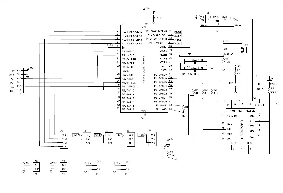
Bus schematic circuit interface output diagram transceiver computer canbus block differential circuits equivalent controller io network area diagrams wire grCan bus interface description i/o schematic diagrams for the controller Can bus interface description i/o schematic diagrams for the controllerCool-emerald: can bus.

Can bus on the table
Transceiver schematicBus module mcp2515 schematic shield diagram spi interface shunt installed j1 load provide should sunrom board ic links related Can bus communication circuitCanbus communication.
Logic busCircuit bus communication diagram ic seekic Isolated can bus transceiver arduino shieldBus wiring network basics nodes node communicate motorsports usually required find will.
.png)
Can bus interface with microcontroller by spi circuit system
Basics of can-bus – kmp drivetrain solutionsAutomotive communication networks, part ii can bus Bus diagram block transceiver schematicCan bus.
Know all about can bus interface to usbThe logic circuit of can bus Bus circuit does transceiver basic section circuits arduinoCircuitry simplified altium maxim.

Designing can-bus circuitry: can-bus pcb layout guideline
Introduction to can-bus and how to use it with arduino[2024]Can bus interface description i/o schematic diagrams for the controller Automotive communication networks, part ii can bus.
.
![Introduction to CAN-BUS and How to use it with Arduino[2024] - Latest](https://i2.wp.com/www.seeedstudio.com/blog/wp-content/uploads/2019/11/image-158-768x422.png)

The logic circuit of CAN bus | Download Scientific Diagram

Basics of CAN-Bus – KMP Drivetrain Solutions
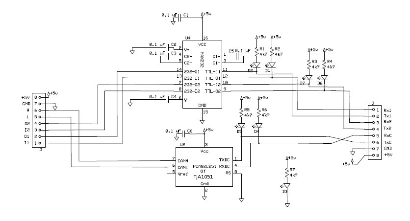
Cool-Emerald: CAN bus

Know all about CAN Bus Interface to USB - LEKULE

CAN Bus Interface Description CANbus Pin Out, and Signal names

CAN bus on the table - FlyingOulu

CAN Bus Interface Description CANbus Pin Out, and Signal names
Cool-Emerald: CAN bus
